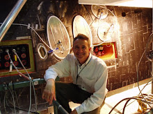
 To the right is a view of the µMRA motor mount. I stuck with 24mm motors for these models because I was comfortable clustering and flying them and didn't expect µMRZ or µMRA to weigh so much some combination of E or F motors couldn't be made to work. RockSim showed a cluster of 4 E30's would carry µMRA and its 3 pounds of ballast off the pad at about 51 ft/sec to an altitude of some 475 feet -- probably with lots of roll, since the only thing to dampen it was those dummy nozzles. I pictured a pyramid rocket sort of flight. Whether it would have worked or not is anyone's guess ... as MLAS evolved I moved on to the next model and µMRA began gathering dust along with µMRZ. It too is a "when I get back to this" project.
The real MLAS team was struggling with propulsion issues ...
Any rocketeer who has flown a motor cluster knows how important it is that all the thrust vectors be closely-coupled and aligned through the CG of the model. If they're not, and a motor fails to ignite at launch, the resulting thrust offset can pinwheel the model off the pad -- this providing the remaining motors provide enough thrust to even get it off the pad. Solid motor ignition is a mature technology and we weren't too concerned about being able to get the four motors in the MLAS cluster to fire, but did worry about what would happen during the burn or at the end as the motors shut down. No two motors are exactly the same, and the thrust offset caused by one firing with slightly more thrust than the others could cause the ship to fly in an unpredictable direction; one firing slightly longer than the others at shutdown could easily overpower the aerodynamic restoring moment offered by the fins and induce a tumble. If we were designing a custom motor for this application we could build a single thrust chamber with multiple nozzles or design-in TVC, but we were limited to the off-the-shelf MK-70's we had available.
We looked hard at a building a manifold that would tie the head-ends of the four motors together and balance pressures between them, essentially making them act as one. And we stayed on that path until "motor manifold" threatened to consume the project ... it quickly became our biggest project risk and the single-costliest piece of hardware we had to design and build. MLAS was about demonstrating an alternate abort concept, not designing a new propulsion system. So we changed direction. We moved the four motors back to the aft in their own "Boost Skirt" and added another set of fins to provide aerodynamic stability for the whole stack. The motors would be canted to fire through the vehicle centerline with the CG offset slightly to provide a ballistic arc over the water. Our test flight would thus simulate the custom-designed propulsion system of an objective vehicle with its Boost Skirt, and the aerodynamic stability feature of such a vehicle with its Coast Skirt. MLAS would demonstrate drogue-assisted turnaround and capsule separation, and employ a variation of Shuttle SRB parachute deployment for capsule recovery.
 MLAS would go through several more design iterations, but the propulsion decision fixed the basic configuration of the vehicle as shown to the left. It also set me on a path to reproduce the ship and as much of the flight as I could in a third-generation MLAS model.
Thus was born µMLAS.
No comments:
Post a Comment